 |
In
the late 1980s, the US military began experimenting with Combat Edge [CE] systems. The
Soviets and the Swedes were using a similar system starting in the 1960s. The CE system
consists of an inflatable bladder in the back & sides of the helmet. When the pilot
pulls heavy G's, the bladder inflates and forces the mask tighter against his face,
thereby keeping a good oxygen seal. The Air Force would take standard 55/Ps and convert
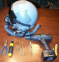
[Tech Order] them to CE by using a separate CE Kit. Tools you will need: Cordless drill;
small Phillips & flat head screwdriver; 1/8 drill bit; 7/16 drill bit; needle nose
pliers; large Phillips head screw driver. |
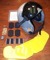
| You
will also need the Combat Edge conversion kit as shown to the right. The kit includes:
Helmet bladder; quick disconnect, female; quick disconnect cover; 2 screws w/ lock washer;
hose clamp; template; Hook & Loop fasteners for the earcups (large pieces); Hook &
Loop fasteners for the TPL (small pieces). The kit also comes with clear and dark MBU-20/P
cut visors (not shown). |
 |
 |
You
will need to remove the left male snap that the visor attaches to and the left nape strap
screw. These two piece will be replaced and will hold the clear template in place. The
earcup on the inside needs to be pulled out as well. |
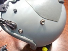
| Shown
here is the clear template in place with the left male snap and the left nape strap screw
put back in the original places. There are holes in the template (marked "A"
& "B")- "A" goes with the visor snap, "B" is where the
nape screw goes. This will place the template in the correct position on the helmet for
drilling. |
 |
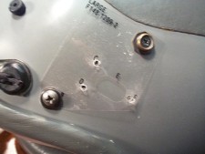 |
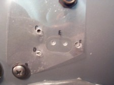
Using
the 1/8" drill bit, drill holes at "C", "D", and
"F" as shown to the left. There are marks on the template where exactly to
drill. It is very important to be accurate in this step because the screws will come
through C & D to meet with the female quick disconnect. |
| Change
to the 7/16" drill bit for this step. In the large oval area marked "E",
make 2 starter holes- each one equidistant from the center and top/bottom. Start on one
side and drill completely through. Then do the next. This should get the area close to
being done. It may take a little clean up work with a file. After the holes are drilled,
trace the "E" area of the template. Then it can be removed for the clean up
work. |
 |
 |
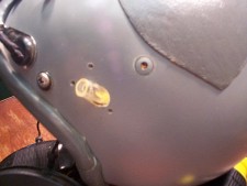
Here
is the hole after the template was removed and prior to the clean up work with the edges.
It looks a little rough, but the cover assembly will hide any minor flaws. Be sure to
replace the nape strap screw and the male visor snap before going further. |
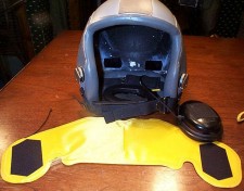
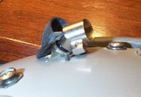
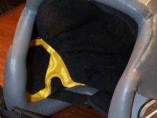
| Dry
fit the bladder in the helmet and check for fitting and make sure the hole works with the
air filler tube (see below photo). You will also want to check where the Velcro (hook
& loop) will need to be placed on the bladder. |
 |
 |
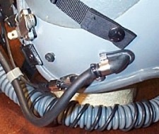
The
angle on the tube looks good here. You will want to make sure that it does not get pinched
in any area. We are about ready to put the female quick disconnect on. One more thing
before that though. |
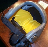
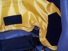
| The
bladder is shown with the hook part (stiff side) of the Velcro attached. The side of the
bladder that is shown up will be facing the back of the helmet. If you look inside the
shell, there are 2 small pieces of Velcro attached- that is where the TPL is held in. You
will have corresponding pieces on each side of the bladder at the TPL attachment points
& at the earcup locations. Sounds confusing, but you are basically putting the helmet
bladder in-between the styrene liner and TPL & the shell and earcups-- you need the
Velcro on both sides of the bladder to reattach everything correctly. |
 |
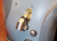 |
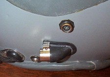
OK,
the bladder is being held in with the Velcro, now we can attach the metal female quick
disconnect [QD]. Make sure to insert the QD in the bladder hose facing the correct way
because it is tight and hard to spin around. Use the hose clamp (a small zip-tie) to
secure the fitting. |
| Push
the 2 screws with lock washers through from the inside. The female QD is threaded and will
act as the nut. We are testing to make sure everything is lined up here. Looks good. |
 |
 |
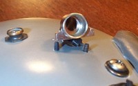
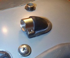
Take
the rubber QD cover, at the end of it is a rubber string and a plug. Pull this through
hole "F" (the back hole). You may need a small screw driver to help insert
the plug. Next place the 2 holes of the QD cover through the screws coming through the
shell. The metal QD will go over the top and hold down the assembly. |
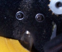
| This
is the view from the inside. You can see the yellow bladder, the bladder hose going
through the shell, the 2 screws with washers, and the nape strap lock nut. Below you can
see the finished QD assembly on the outside of the shell. Note how the front of the QD
cover is being held down by the metal QD. |
 |
 |
 |
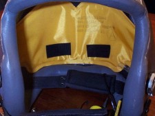
| Back
to the inside now. Shown here you can see the Velcro pieces in the correct position.
Visualize on the other side of the bladder the corresponding pieces in the same location
holding the bladder in. These pieces shown here will hold in the earcups & TPL. |
 |
 |
Inside
the back of the helmet, these 2 pieces of "stiff side" velcro will hold the TPL
liner in place. |
| Shown
here, the TPL has been replaced. All that is left to do now is replace the earcups. |
 |
 |
The
MBU-20/P CE mask is attached and the air feeder hose is plugged into the metal QD on the
helmet- perfect fit. The helmet is now an HGU-55/P Combat Edge. |
| With special thanks to Trey Turner of CSA for the permission to publish
this guide at Flightgear on-line. Source:
Check 6 Aviation |